Inquiry
Form loading...
010203
01 / 03
010203

PRODUCT

Introduces the advanced international production technology and high quality raw materials for the ceramic products.

Full Automatic Radiator Production Line Full Automatic Radiator Production Line
04

Full Automatic Radiator Production Line

2024-06-19

I. General

Our automatic radiator (for transformer) production line mainly absorbed, improved & updated the European technology and design. Our machine performance reaches the international standard class, and the price is much economic and competitive. The whole line is composed of automatic decoiler, roll former, hydraulic press machine, rotate rack, spot welding machine, dual seam welding machine, end welding machine, edge shearing machine, end cutting machine, panel straightening machine and forwarding conveyers, etc. The sizes of radiators are 320, 460, 480, 520, 535, or custom-design (as per client’s actual requirement). Panel length is 1000 - 4000 mm. The whole line is fully automatic, the product quality is good, and the performance reaches the first-rate in the world.

II. Work flow

Automatic Decoiling – Roll forming and Hydraulic Pressing – Automatic Rotating – Spot Welding – Seam Welding –– End Welding 1 –– End Welding 2 – Edge Trimming – End Cutting –Panel Straightening

Item

Data

Standard panel size

310mm, 320mm,460mm, 480mm, 520mm, 535mm, etc

Panel length

1000-4000mm

Length tolerance

±1.0mm

Panel bearing pressure

Positive pressure≥ 0.15Mpa,negative pressure ≥ 133Kpa,without deformation

Panel material

ST12, SPCC, DC01 cold rolled steel, 1.0-1.2mm

Line work speed

2-6m/min

Oil fluits size

Steel thickness 1.0mm

≥ 11mm

Steel thickness 1.2mm

≥ 11.5mm

Number of oil fluits

Panel 310mm, 320mm

3

Panel 460mm, 480mm

5

Panel 520mm, 535mm

6


view detail
Corrugated Fin Forming Machine Corrugated Fin Forming Machine
08

Corrugated Fin Forming Machine

2024-06-13

Corrugated fin forming machine is used to produce corrugated plate for transformer wall. The work flow is uncoiling – feeding – folding – pressing – cutting.


Corrugated fin forming machine is used to produce corrugated plate for transformer wall. The work flow is uncoiling – feeding – folding – pressing – cutting.

Description:

The main power of the corrugated fin forming machine is hydraulic.Hydraulic pump motor use Siemens brand motor, and all valves and pump are using Yuken brand products with very high quality.

The feeding and length measuring adopt servo motor and grating scale , with high precision and high automation. No need manual operation to change the sizes. The machine adopts PLC automatic controlling, touch screen operating. The corrugated plates made by this machine are with high quality and high precision.

Features:

Schneider PLC system with touch screen operating

Durable high quality hydraulic power system

Delta servo motor precision feeding system

Enhanced high strength machine structure

Main Technical Data

Machinetype

A1300x400

A1600x400

Suitable materialthickness

1-1.5mm

1-1.5mm

Formingwidth

300-1300mm

300-1600mm

Finheight

50-400mm

50-400mm

Pitchdistance

45-80mm

40-100mm

Corrugated platelength

300-2000mm

300-2000mm

Workingspeed

Approx. 22s perfin

Approx. 22s per fin

Main Hydraulicpower

22KW+30KW, 2motors

22KW+30KW, 2 motors

Hydraulicpressure

2-20Mpa

2-20Mpa

Feedingpower

Servo motor 2KW, pinch roll for feeding

Servo motor 2KW, pinch roll for feeding

Fin heightmeasuring

Gratingscale

Grating scale

Cutting

Hydrauliccutting

Hydraulic cutting

Cooling

Industrial air condition typecooler

Industrial air condition

Controlling

SchneiderPLC

SchneiderPLC

Touchscreen

Schneider 10inches

Schneider 10inches

Totalweight

12 tonsapprox

20tonsapprox

view detail
CRGO Silicon Steel Slitting Line CRGO Silicon Steel Slitting Line
010

CRGO Silicon Steel Slitting Line

2024-06-06

 Introducing our most advanced CRGO silicon steel slitting production line - the ultimate solution for precision longitudinal slitting of electrical silicon steel coils.  This cutting-edge machine is designed to efficiently and accurately cut wide coil sheets up to 1250 mm wide into strip coils of the required width, making it an indispensable tool for the transformer industry.

 At the heart of our CRGO silicon steel slitting lines is advanced technology that ensures the highest level of precision and consistency in the slitting process.  This means our machines can deliver strip coils of the required width, meeting the stringent quality standards of the electrical and transformer industries.

 One of the key features of our CRGO silicon steel slitting lines is the ability to handle large volumes of steel coils easily and efficiently.  This makes it ideal for manufacturers with stringent production requirements, allowing them to streamline operations and increase overall productivity.

 In addition to its impressive performance, our CRGO silicon steel slitting lines are designed with user-friendly controls and an intuitive interface, making them easy to operate and maintain.  This ensures operators can adapt to the machine quickly, minimizing downtime and maximizing output.

 Additionally, our slitting lines are designed with durability and longevity in mind, using high-quality materials and components to withstand the rigors of continuous operation.  This makes the machine reliable and robust, capable of delivering consistent performance over the long term, providing our customers with a solid return on investment.

 Our CRGO silicon steel slitting lines are versatile and can be customized to meet specific production requirements.  Whether adjusting coil width or accommodating different types of electrical silicon steel, our machines can be customized to individual needs, providing flexibility and adaptability during the manufacturing process.

 In summary, our CRGO silicon steel slitting production line is a cutting-edge solution for the transformer industry, providing precise, efficient and reliable performance in longitudinal slitting of electrical silicon steel coils.  With its advanced technology, high throughput, user-friendly design and customization options, it is ideal for manufacturers looking to optimize their production processes and consistently deliver high-quality coils.

view detail
CRGO Silicon Steel Coil Slitting Line For Transformer Core Production CRGO Silicon Steel Coil Slitting Line For Transformer Core Production
011

CRGO Silicon Steel Coil Slitting Line...

2024-06-06

Item

Value
Steel thickness 0.18-0.5
Decoiling expansion range Φ480-Φ520mm
Material width 200-1250mm
Coil weight ≤5000kg
Slitting shaft Φ125mm
Blade outer diameter Φ250mm
Slitting strip width 40-1200
Slitting speed 80-120m∕min
Burr ≤0.02mm
Straightness ≤0.2mm/2m
Width tolerance ±0.1mm
Slitting blade 6 sets
Power consumption 55kw
Gross weight About 20 ton
Power supply 380V AC 50Hz


Main Components and Parameters:

1. Coil Car for Loading and Unloading

The coil car can move and elevate. It can load the coil into decoiler or unload the coil strips from recoiler. It mainly consists of trolley, wheels, shafts, hydraulic system etc.

2. Decoiler

Decoiler mainly consists of machine base, reducer, main shaft, supporter, etc. It can be expanded by hydraulicsystem, and motor for forwarding and backward.

Coil inner diameter: 500mm

Max. outer diameter: 1200mm

Coil weight: 5000kg

Expanding range: 480-520mm

Max. coil width: 1000mm

3. Slitter

It is the most important device in the slitting line. It mainly consists of shaft, reducer, blade, machine base, guidingstructure, etc.

Slitting width tolerance: ±0.1mm

Max. slitting speed: 80-120m∕min

Slitting thickness: 0.15~0.5mm

4. Tensioning unit

This device is used to provide tension force to the steel sheet. So the coil can be rewind tightly and orderly. It mainly consists of supporter, roll, press plate, separator, etc

5. Recoil

The recoiler is used to rewind the strips into rolled coil and then the coil strips can be unloaded by coil car. It mainly consists of machine base, reducer, motor, shaft, press roll, etc

Recoiling inner diameter: 500mm

Max. recoiling width: 1000mm

Loading capacity: 5000kg

Outer diameter: 1200mm

6. Hydraulic system

The hydraulic system is used for the power source of the hydraulic cylinders. It mainly consists of oil pump, tank, cooler, valves, etc


view detail
Silicon Steel(CRGO) Slitting Line Silicon Steel(CRGO) Slitting Line
012

Silicon Steel(CRGO) Slitting Line

2024-06-06

 Introducing our state-of-the-art slitting line, designed to meet the specific needs of the electrical industry.  This advanced machinery is designed to precisely cut wide CRGO coils into strips of the required width, which are then wound into rolled coils with the utmost precision and efficiency.

 Our slitting lines are an indispensable tool for manufacturers of transformers, motors, transformers and reactors.  It is carefully crafted to ensure that the materials processed meet the highest quality and performance standards.

 Our slitting lines are equipped with cutting-edge technology to provide unparalleled precision and consistency in longitudinal cuts of CRGO membranes.  This produces strips of uniform width that meet the customer's exact specifications.  The ability to achieve this level of accuracy is critical to ensuring optimal performance of the final product using these strips.

 Additionally, our slitting lines are designed for seamless operation, maximizing productivity and minimizing downtime.  Its user-friendly interface and automated features make it easy to operate, reducing the need for extensive training and streamlining production processes.

 In addition to technical capabilities, our slitting lines are designed with durability and longevity in mind.  It is constructed from high-quality materials and components and is designed to withstand the rigors of industrial use, ensuring long-term, reliable performance.

 At [Company Name], we are committed to providing cutting-edge solutions to the electrical industry, and our slitting lines demonstrate this commitment.  With its precision, efficiency and reliability, it promises to become an indispensable asset for manufacturers looking to increase production capabilities and provide quality products to their customers.

 Experience the difference our slitting lines can make to your operation.  Contact us today to learn more about how this advanced machinery can benefit your business and take your production processes to the next level.


Main Features:
1. Adopting advanced pull slitting and active slitting process with high precision
2. Adopting a high-rigidity, high-precision structure of the slitter and recoiler. The design deflection of the main shaft system is 0.01%.
3. The layout of the line is reasonable. All use electric, pneumatic or hydraulic driving. It’s easy to operate and has high production efficiency.
4. Adopting advanced Omron PLC from Japan to achieve the logic control of the whole line and increased the stability and reliability of the system. Human-Computer dialogue is available through touch screen, fixed length cutting and cutting speed are all displayed on the screen.
5. The slitting speed is adjustable. The uncoiler, slitter and recoiler all adopt imported speed governor. Single operation, uncoiler and slitter linkage, uncoiler, slitter and recoiler three machine linkage can be realized when in manual state, the slitting speed will be matched automaticly. The whole line speed is synchronization when automatic cutting.

view detail
High-Performance Longitudinal Cutting Line for CRGO Steel Coil High-Performance Longitudinal Cutting Line for CRGO Steel Coil
013

High-Performance Longitudinal Cutting...

2024-06-06

In the production of transformers, precision and efficiency are crucial factors. This is where the transformer slitting line plays an important role. At our company, we offer state-of-the-art slitting lines specially designed for the transformer industry. Our machines offer a range of advantages, making them ideal for businesses looking to enhance their production processes.

One of the main advantages of our slitting lines is their high level of cutting precision. This is achieved through the use of high-precision slitting machines, ensuring the material is cut with the highest precision to meet the precise specifications required for transformer production. The result is a high-quality end product that meets the industry’s strict standards.

In addition to precision, our slitting lines offer low-burr and low-bend slitting processes. This is crucial for transformer production as it ensures the material is cut cleanly without any distortion. The high-speed production capabilities of our machines further increase efficiency without compromising the quality of the final product.

Automation is another key feature of our slitting lines. The machine is equipped with electrical, pneumatic and hydraulic systems that work together to ensure a high level of automation. This not only improves the overall efficiency of the production process, but also reduces the need for manual intervention, thereby minimizing the risk of errors.

The thickness range of our slitting lines is another differentiating point. Capable of processing materials with thicknesses between 0.18 and 0.5 mm, our machines are versatile, allowing businesses to process a variety of materials without the need for multiple machines.

In addition, our slitting lines are equipped with optional equipment such as scrap winders and hydraulic cutters. These additional features give businesses the flexibility to tailor the machine to their specific production needs, further enhancing its overall functionality and efficiency.

So why choose us for your slitting line needs? Our machines are designed to meet the unique requirements of the transformer industry, combining precision, efficiency and versatility. Specializing in high-precision cutting, low-burr and low-bend slitting, automation and optional configurations, our slitting lines are ideal for companies looking to optimize their transformer production processes. Contact us today to learn more about how our slitting lines can benefit your business.

view detail
Georg Analogue CNC Step-Lap Transformer Core Cutting Machine with Swing Shear Georg Analogue CNC Step-Lap Transformer Core Cutting Machine with Swing Shear
014

Georg Analogue CNC Step-Lap Transform...

2024-05-28

3003SILICON STEEL SHEET SHEARING EQUIPMENT 

cutting machine (10).jpg

1.The system device realizes the function

1.The system can complete the automatic production of straight slit.oblique slit.right Angle plus bevel.parallelogram and other iron chip type.and automatically complete the cutting.corner.counting.punching.punching V-port work. The device is equipped with three -.five - and seven-step functions.

2.The system can realize the automatic input of silicon steel sheet coil material and the automatic output of processed parts (automatic feeding,automatic discharging,automatic sorting

,positioning and correction functions).

cutting machine (4).jpg

cutting machine (7).jpg

2. System equipment main composition and other

1. Fixed and transmitted parts of silicon steel sheet coil

1) Hydraulic discharge machine (placing silicon steel sheet coil).its carrying capacity of 2T.the inner diameter of the coil size range of 450~550mm.the maximum width of 300mm.

2) The feeding machine is equipped with feeding motor and inverter.and automatically adjusted by the sensor to ensure the normal transmission of the silicon steel sheet coil.

3) AC servo system with PLC module to achieve high precision size feeding.requiring fast response.high positioning accuracy.low noise.low heat loss.long life and other characteristics.and to ensure the speed and accuracy of feeding.

cutting machine (8).jpgcutting machine (9).jpg

2.Silicon steel positioning mechanism

1) Workpiece positioning part: using the lead screw linear guide rail center positioning.to ensure the use of accuracy and life.

2) The positioning of the workpiece should be firm and reliable to prevent the deviation of the workpiece in the transmission process; The center of workpiece width coincides with the center of lead screw guide. The minimum width is 40mm and the maximum width is 300mm.

cutting machine (1).jpgcutting machine (2).jpgcutting machine (3).jpgcutting machine (13).jpgcutting machine (17).jpgcutting machine (18).jpgcutting machine (20).jpgcutting machine (21).jpgcutting machine (23).jpg


Name full automatic swing-shearer step lap transformer core cut machine 

VPI Plant (2)chinese machineVPI Plant (1)

view detail
Busbar Automatic Assembly Line busduct equipment compact Busbar Automatic Assembly Line busduct equipment compact
015

Busbar Automatic Assembly Line busduc...

2024-05-28

Bus punching machine adopts six-axis control, servo clamp, is a kind of automatic feeding, automatic positioning, automatic clamping, automatic punching. Automatic shift, automatic feeding and other perfect combination of high degree of automation, accurate positioning, easy to use numerical control equipment. Widely used in high and low voltage switchgear, transformer manufacturing, box type substation, bus slot and other industries, for various specifications of copper, aluminum busbar automatic processing, has the advantages of high degree of automation, fast processing speed, high precision, is the ideal equipment for bus processing.

1.Main parameters of host equipment of busbar cutter:

NAME

UNIT

PARAMETER


THE NOMINAL FORCE

CUT CELLS

KN

600

PRESSURE FLOWER UNIT

KN

600

THE PUNCHING UNIT

KN

600

X1 (FEEDING SHAFT), X2 AXIS (WORKPIECE DRAG SHAFT) TO POSITION THE MAXIMUM SPEED

M/MIN

65

X1 AXIS MAXIMUM STROKE (DISCHARGE)

MM

2000

X2 AXIS MAXIMUM STROKE (FEED)

MM

300

MAXIMUM EFFECTIVE TRAVEL OF THE Y-AXIS

MM

530

Z-AXIS MAXIMUM STROKE

MM

350

STRIKE CYLINDER TRIP

MM

50

CRACKDOWN FREQUENCY

HPM

160

WORKPIECE OPERATION STRIKE FREQUENCY

HPM

120


MODULE

PUNCH DIE (OPTIONAL)

COVER

6

7

SHEAR DIE

COVER

1

1

EMBOSSING DIE

COVER

1

1

SERVO CONTROL AXIS NUMBER


6

THE ACCURACY OF APERTURE CONTROL

MM/M

±0.20


A SINGLE STROKE IS ALLOWED WITH A MAXIMUM DIAMETER


MM


F32


ONE-TIME PRESSURE-FREE CROSS-SECTIONAL AREA


MM²


200×60

MAXIMUM ALLOWABLE PLATE (LENGTH, WIDTH AND THICKNESS)

MM

6000×200×16

HOST WEIGHT MEASURE

KG

5300

MAIN ENGINE STATION SITE AREA: LENGTH AND WIDTH

MM

7300×3100

MAXIMUM LIQUID PRESSURE

MPA

31.5

TOTAL MOTOR POWER

KW

22.5

FAQ

Q: How about after-sales service?

A: 1.We can provide free training in our company.

2.If u need, our engineers are available to service machinery overseas.


Q: How about the warranty?

A: The complete machine has a one-year warranty and Life time maintenance.


Q: What should I do when I have some problem or question?

A: Pls don't hesitate to contact us, we will reply u ASAP.


Q: How about the quality?

A: Before we pack each machine, we will test it first. If machine has problem in your place, our worker will take responsible for his mistake. And we will solve your problem.


Q: Which is the most suitable model machine for me?

 A: Pls tell us your materials, thickness, size and business industries.We will select the machine model that is right for you.


Q: Why choose us?

A:1.We have a technical team of over 50 people with years of rich work experiences.

2.Comprehensive after-sales service.

3.quality assurance.Conducting multiple inspections and debugging after the installation of the machine, and continuously updating the fault section.

4.We have 26 years specialization in transformer&CTPT industry

5.We are sourcing factory with no middle charge of the price.


view detail
010203
010203
010203

About us

YIBO Machinery Co., Ltd.

YIBO Machinery Co., Ltd. is a professional enterprise who specialized in manufacturing automatic equipment.  It is located in Gaoxin industry area, Pingxiang City, Jiangxi Province, China.  YIBO mainly manufacture all kinds of transformer manufacturing equipment:  Vacuum equipment (Oven, VPI, Casting plant), Transformer foil winding machine, HV and LV winding machine, Transformer processing machine, Core winding machine, Silicone steel cutting machine, Busbar processing machine, APG Machine, Mold, CT/PT winding machine, Laser Marking Machine, Testing machine, Electrical porcelain insulator production line, vacuum circuit breaker production line, Core Cutting Line, CRGO Slitting Line etc.
  • 20
    years
    Year of establishment
  • 300
    +
    Number of employees
  • 20
    +
    Cooperative companies
view more

SERVICES AND ADVANTAGES

The project work of our company has always been entrusted to YIBO Company. The team of our company is very serious and dedicated, and there has never been any mistake. Thank you very much! I hope to cooperate with YIBO company all the time!

Latest News

Transformer high and low voltage insulation resistance how many is qualified? Transformer high and low voltage insulation resistance how many is qualified?
01
2024-06-19

Transformer high and low voltage insu...

The insulation resistance of power transformers in operation is qualified by: 10KV class and below, the insulation value is greater than 300 megohm: 35KV class, the insulation value is greater than 400 megohm (the ambient temperature is 20℃).

Through the measurement of insulation resistance, power transformers can effectively find some insulation problems and other problems of transformers, such as winding touching the shell, touching the core, short circuit between the coils, etc. So during regular maintenance or after overhaul. Always measure insulation resistance. When measuring the insulation resistance of the transformer, it is generally necessary to measure the insulation resistance between the high voltage coil and the shell, the low voltage coil and the low voltage coil, and the insulation resistance of the core screw to the iron core should be measured when the hanging core is repaired. 2500V megohm meter is generally used to measure the insulation resistance of power transformers, but 1000 megohm meter is generally used to measure the insulation resistance of the core screw to the iron core.

The insulation resistance of power transformer is greatly affected by humidity and temperature. When the humidity increases, the surface and interior absorb water, the leakage current increases, and the insulation resistance decreases. When the temperature rises, the charged particles are easily conductive due to the strengthening of thermal motion, the leakage current increases, and the insulation resistance decreases. Therefore, the resistance value of the insulation resistance measured at different temperatures is different, and the higher the temperature, the lower the insulation resistance.

Standard for insulation resistance of transformers

1. Insulation should be measured before the transformer is put into operation after newly installed or overhauled and after long-term disuse (three weeks).
2, the voltage level of more than 1000V winding use 2500V dial, 1000V dial winding below 1000V. The resistance value is specified (20℃) for 300MΩ in 3-10KV, 400MΩ in 20-35kV, 800MΩ in 63-220KV, and 3000MΩ in 500KV. The resistance of 500V dial for transformers with voltage 0.4KV and below is ≥0.5MΩ.
3, when the resistance value is less than 50% of the previous value, notify the maintenance treatment, if necessary, measure the dielectric loss and absorption ratio of the transformer. Absorption ratio R60 "/R15", the ratio is not less than 1.3.

Name of insulation resistance:

High to low ground: (primary winding to secondary winding and housing) high voltage winding to low voltage winding and housing insulation resistance;
Low to high ground: (secondary winding to primary winding and housing) insulation resistance of low voltage winding to high voltage winding and housing;

Insulation resistance qualified value standard

(1) The insulation resistance value measured this time is compared with the last measured value at the same temperature, and the value should not be reduced by 30% compared with the last value;

(2) The absorption ratio R60/R15 (the ratio of insulation resistance at 60 seconds and 15 seconds in telemetry), should be 1.3 and above at 10 ~ 30℃ :

(3) For a transformer with a primary side voltage of 10kV, the minimum qualified value of its insulation resistance is related to temperature. Relation between insulation resistance of transformer and temperature at test time
Transformer insulation resistance calculation formula: Use the formula to calculate the insulation resistance at each temperature "rising ten half, reducing ten double, good multiplied by one and a half" absorption ratio: R20 = Rt X 10t-20/40 temperature rises 10OC, Rt X 2/3 times. Rt X 1.5 times for every 10OC drop in temperature.

4, the newly installed and overhauled transformer, its insulation resistance qualified value should comply with the above provisions. Transformers in operation are no less than 10 megohm.

READ MORE
What kinds of transformers are commonly used? What are the characteristics of each? What kinds of transformers are commonly used? What are the characteristics of each?
02
2024-06-19

What kinds of transformers are common...

The types of transformers are varied, but as far as their working principle is concerned, they are made according to the principle of electromagnetic induction. In general, the classification of commonly used transformers can be classified as follows.

(1) By use:

1) Power transformer: used to boost or buck the power system, is one of the most common and most commonly used transformers:
2) Test transformer: generate high voltage, high voltage test with electrical equipment:
3) Instrument transformers: such as voltage transformers, current transformers, used for measuring instruments and relay protection devices:
4) Transformers for special purposes: furnace transformers for smelting, rectifier transformers for electrolysis, welding transformers for welding, voltage regulation transformers for testing, etc.
(2) According to the number of phases:

1) Single-phase transformer: for single-phase load and three-phase transformer group:

2) Three-phase transformer: used for raising and lowering voltage of three-phase system.

(3) According to the winding form:

1) Autotransformer: used to connect ultra-high voltage, large capacity power systems:
2) Double-winding transformer: used to connect two voltage levels of the power system;

3) Three-winding transformer: used to connect three voltage levels, generally used in regional substations of power systems

(4) According to the core form:

1) Core transformer: for high voltage power system:
2) Shell type transformer: special transformer for high current, such as electric furnace transformer and welding transformer, etc. : or power transformer for electronic instruments and TV, radio, etc

(5) According to the cooling method:

1) Oil-immersed transformer: such as oil-immersed self-cooling, oil-immersed air cooling, oil-immersed water cooling, forced oil circulation and water internal cooling, etc. :
2) Dry transformer: rely on air convection for cooling, the current indoor power transformer, the sample is cooled by fan:
3) Inflatable transformer: use special gas (SF6) instead of transformer oil heat dissipation;
4) Evaporative cooling transformer: use special liquid instead of transformer oil for insulation and heat dissipation.

READ MORE
Transformer vacuum oil filling and oil filtering operation Transformer vacuum oil filling and oil filtering operation
03
2024-06-13

Transformer vacuum oil filling and oi...

(1) The purpose of vacuum oil injection

Vacuum oil injection can greatly reduce the content of transformer oil and water, thus greatly enhancing the breakdown strength of transformer oil, that is, reducing the oil gap distance of the body insulation, resulting in greatly reduced transformer design costs.


Attention:

Transformer oil filtration and oil injection should be carried out in fine weather. Transformer drain valve port should be matched with the oil filter inlet pipe port.

Oil filter should be filled with vacuum tank oil standard tube 1/2 qualified oil.


(2) transformer oil filter in operation

Open the oil pillow cover of the transformer, insert the oil filter outlet pipe under the oil level on the oil pillow, and then seal the oil pillow cover with clean filter paper or film.


Insert the inlet line of the oil filter into the oil drum prepared with qualified oil.

Open the oil drain valve at the bottom of the transformer and drain 3-5% of the oil of the transformer (3-5% of the oil is mainly impurities and water, and should be stored separately.


After the oil drain valve at the bottom of the transformer is discharged by 3-5%, the oil filter is pumped into a high vacuum (not less than -0.09Mpa) and the oil level of the transformer oil pillow meets the requirements, the oil inlet pipe of the oil filter is connected to the oil drain valve. At this time, the oil filter can work normally.


After the hot oil circulation of the transformer is completed and the oil injection is completed, it should be left standing for a period of time before applying the voltage. 110KV needs to stand for 24h; 220KV needs to stand for 48h.


Note: After the transformer is resting, it should be vented several times from the transformer's bushing, elevating seat, cooling device, gas relay and pressure release device, and should start the submersible oil pump until the residual gas is exhausted.


(3) Oil injection of newly installed transformer

Oil filter and newly installed transformer vacuum

After all transformer accessories are installed. Open all valves of the connecting body of the accessories and components, and vacuum all accessories (including coolers and radiators) except the oil storage tank and gas relay. If the oil storage tank is designed in full vacuum, the oil storage tank and gas relay are also vacuumed.


When vacuuming, close the vacuum valve on the transformer body, check that the vacuum pipe system does not leak, and open the vacuum valve to vacuum the transformer. After the vacuum degree of the transformer reaches the specified value, the vacuum holding time can be filled with vacuum oil only after the specified time is reached (generally keeping the vacuum for 3 to 8 hours is conducive to moisture volatilization).


Vacuum oiling

The transformer oil must be injected into the transformer after the oil sample test is qualified according to the current national standard "Electrical Equipment installation Engineering Electrical equipment handover test Standard".


After checking that all parts are normal, open the oil inlet valve of the oil filter device and the oil outlet valve of the oil tank. After the insulating oil enters the oil tank of the oil filter device, turn on the heater.


After the liquid level in the oil tank reaches the observation window position, open the oil outlet valve and the oil filling valve of the transformer, and open the oil outlet pump to fill the transformer with oil (in order to ensure that the oil is clean and free of impurities, a small amount of oil can be discharged before filling the transformer to clean the tubing and connecting accessories).


The oil injection speed should not be greater than 1800L/h, and the transformer is vacuumed while the oil is injected.


Fill the oil to the specified oil level of the oil storage tank, and the corresponding temperature position should be slightly higher according to the temperature curve of the oil level.


The oil filling is finished, and the shutdown operation is the same as that of oil filtering.


After oil injection, it should continue to maintain direct air, holding time :110kV transformer shall not be less than 2h, 220KV transformer shall not be less than 4h.


Transformer hot oil cycle operation

Hot oil circulation must be carried out after vacuum oil injection for transformers with voltage grades of 220kV and above. Cycle time: 110kV transformer general hot oil cycle 24 hours, 220kV transformer should not be less than 48 hours.


Connect the oil filter to the transformer, connect the oil filter inlet pipe to the bottom valve of the transformer, the outlet pipe to the top valve of the transformer, and the hot oil is injected from the top of the transformer.


Start the oil filter vacuum pump, first open the oil filter side inlet valve and outlet valve, use the oil filter vacuum pump to evacuate the air in the oil pipe, and then open the valve at the bottom of the transformer for circulating transformer heating.


Hot oil circulation precautions:

Before hot oil circulation in full oil state, check that the moisture absorber is correctly installed and breathing is smooth.


When the hot oil is circulating, the outlet oil temperature of the oil filter should not be lower than 50 ° C, and the temperature in the tank should not be lower than 40 ° C.


After the oil sampling inspection of hot oil circulation, it should meet the provisions of the current national standard "Electrical equipment handover test Standard for Electrical equipment Engineering".


After the hot oil circulation of the transformer is completed and the oil injection is completed, it should be left standing for a period of time before applying the voltage. 110KV needs to stand for 24h; 220KV needs to stand for 48h.


After the transformer is static, it should be vented several times from the transformer bushing, elevating seat, cooling device, gas relay and pressure release device, and should start the submersible oil pump until the residual gas is exhausted.

READ MORE
How do transformers filter and fill oil How do transformers filter and fill oil
04
2024-06-13

How do transformers filter and fill oil

The main function of insulating oil is insulation and heat dissipation, insulating oil first requires good insulation performance, that is, high breakdown voltage, small dielectric factor, which affects the breakdown voltage of the main factors are water, impurities, gas and so on. Transformer oil in operation and the newly installed oil in the long-term storage process is difficult to avoid water intrusion, the operation of the oil under the action of the arc is also easy to produce carbon black, while due to the aging of the oil is also easy to produce impurities such as sludge. The performance of insulating oil is reduced and the safe operation of transformer is affected. At this time, it is necessary to purify the insulating oil to remove the water and various impurities in the oil.


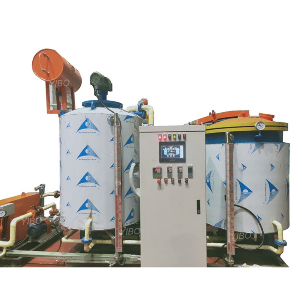
The vacuum oil filter device is a device for the purification of insulating oil, which can efficiently remove water, gas and impurity particles in the oil, improve the insulation strength and oil quality, ensure the safe operation of electrical equipment, and has the functions of hot oil circulation, vacuum oil injection and vacuum pumping for electrical equipment.


1. Working principle of vacuum oil filter device

Before oil filtration, the coarse impurities are filtered from the oil inlet through the initial filter under the action of pressure difference, and the impurities containing particles are heated into the vacuum separation tank through the heating tube. Under the action of the special degassing element of the vacuum cylinder, the insulating oil is fully thin film, and the oil is divided and recombined, so that the tiny water is condensed together into a larger volume of water in the condenser. When the vacuum degree is -0.09Mpa, the boiling point of water is only about 40 ° C, and the oil has been heated and stabilized at 60 ° C, the water in the oil boils out, the oil and water are separated, and the rest of the water vapor and the harmful gases in the oil are discharged by the vacuum pump. The water removed oil is removed by the discharge pump through the fine filter to filter out the particulate impurities, complete a working cycle, after a short cycle, the water, gas and impurities in the oil will be removed to meet the use standard.

2. Vacuum oil filter operation process

(1) Check and prepare before starting

The equipment is placed smoothly, and the oil inlet pipe of the equipment is connected with the oil outlet of the oil tank to be filtered, and the oil outlet of the equipment is connected with the oil inlet of the oil storage barrel. If there is a large amount of precipitation in the tank or oil drum, do not directly insert the tubing to the bottom, if necessary, install pre-filtration.

The cooler is connected to the cooling power supply, in accordance with the principle of the bottom into the top out, small flow water circulation. If it is used for a short time, the water content in the oil is not high, or when it is used in winter, it can also be used without cooling water.

Open the electric control box, select the corresponding three-phase cable according to the total power, switch on the power and ground the vacuum oil filter reliably.

Start the power supply, the power indicator lights up; If the alarm alarm, it means that the phase sequence of the incoming line power line is reversed, (some do not have an alarm, you can observe the positive and negative rotation of the motor, if the motor is reversed, the phase sequence is also reversed) Only need to replace any two wires in the three-phase line.

Safety fences should be placed in the working area, and fire fighting water sources and fire fighting equipment should be provided.

(2) vacuum oil filter operation

The oil storage tank can be filtered by pouring the tank oil filter, and the oil to be filtered through the high vacuum oil filter is all filtered into the oil storage tank, and the oil storage tank is self-circulating, and the oil tank should be sealed. Moisture and magazines in the air are prohibited from entering the oil storage tank.

First, close the inlet and outlet oil valves and other blowdown valves connected with the outside world, sampling valves, water discharge valves and air mixing valves, etc., and then start the vacuum pump on the control panel to begin to vacuum the oil filter device. Vacuum degree rises to set value.

Observe the vacuum gauge on the device, when the vacuum degree is -0.06-0.08mpa, slowly open the oil inlet valve and start to feed oil.

Note: When opening the valve, it should be opened gradually and slowly to avoid damage to the initial filter element due to sudden increase in impact force.

Observe the observation window on the vacuum tube. When the oil enters the vacuum tank and the oil level reaches the middle position of the observation window, open the oil outlet valve first, then start the oil pump, and the oil outlet starts to discharge oil.

Note: If the oil valve is not opened, starting the oil pump first will cause excessive pressure at the oil outlet, resulting in device shutdown and even damage to the filter device.

Adjust the inlet and outlet valves properly, when the inlet and outlet oil reach the basic balance, open the heating switch, start the heater, adjust the temperature control value, generally 55-65℃ is appropriate. If it is a two-stage heating device, it can be decided whether to turn on another set of heaters according to the amount of oil treated and the ambient temperature. The temperature of the secondary heater is slightly higher than that of the primary heating temperature by 3-5℃. (Two stages of heating can also be opened at the early stage of the cycle to facilitate rapid heating, and a group can be closed after the overall oil temperature reaches more than 50 ° C to save energy).

After keeping the circulation filtration for a period of time, open the sampling valve and take the oil sample. (Before sampling, drain a small amount of oil to flush the sampling port and sampling tubing, and the sampling bottle also needs to be cleaned with oil). Until the insulation oil test qualified.

(3) Shutdown operation

Before stopping, turn off the heater 3-5 minutes in advance and keep the oil circulating for a period of time, so that the temperature drops below 50 ° C, otherwise it is easy to damage the heater.

Close the outlet valve of the oil tank first, and then close the inlet valve of the vacuum oil filter. After discharging the remaining oil in the equipment as much as possible, close the oil pump first, and then close the oil valve.

Close the vacuum pump after draining the oil from the tubing. Open the intake valve and remove the vacuum.

Open the valve at the lower end of the condenser, discharge the residual oil or water inside, if you do not need to drain the cooling water for a long time (please be sure to drain the cooling water in winter to avoid freezing). Close the valve when drained.

Open the drain valve, drain the remaining oil in the tank, and then turn off the power.

READ MORE
Analysis and discussion on leakage of transformer oil Analysis and discussion on leakage of transformer oil
05
2024-06-06

Analysis and discussion on leakage of...

■ Analysis and discussion on the leakage of transformer oil


With the development of the power industry, how to improve the performance of power equipment and ensure the reliable operation of the power system is an urgent problem that needs to be solved in power production. Therefore, whether the leakage of transformer oil can be timely and thoroughly dealt with has gradually become an important technical indicator to measure the development of the power industry. The phenomenon of oil leakage in oil-immersed power transformer is quite common in power system. If there is oil leakage in transformer, it may affect the safe and stable operation of transformer. How to solve the problem of leakage oil of transformer is a big problem in the production practice of power sector for many years.


1. Analysis of the causes of transformer oil leakage


According to operation experience, transformer leakage oil generally occurs in the following seven main parts: ① the body large cover connection surface; ② Radiator; ③ Sampling valve; ④ casing; ⑤ tubing flange face; ⑥ transformer base interface; ⑦ Gas relay, etc. It can be found that most of the leakage points are flange joints, seals and valves. Unreasonable flange structure, poor sealing material quality, poor processing technology, changes in the external environment temperature, pressure, etc. will cause leakage of the transformer. These factors complement each other and have a common impact. When there is a problem in one of the links, it will cause a chain reaction, resulting in the occurrence of leaking oil. In practice, the following specific analyses are carried out:


First, the flange surface manufacturing process is unreasonable, and the leakage point at the oil drain plug of the transformer radiator interface accounts for more than half of the total leakage point. The reasons of leakage are: (1) there are corrosion, burr, groove and other phenomena on the contact surface; (2) No sealing groove, unlimited pin; (3) Paint and other dirt on the contact surface; When dealing with paint debris, it may scratch scars on the sealing surface; (4) The position and tightness of the sealing ring are completely determined by experience, and too loose and too tight may lead to leakage.


Second, the most commonly used sealing material is butyl rubber, which is made of sealing rings and gaskets with poor oil resistance and faster aging speed, especially at high temperatures, which can easily cause aging cracking and loss of elasticity. In addition, due to the uneven finish of the sealing surface during the installation process, the compression amount is increased and the leakage is caused.


Third, the transformer shell manufacturing process and material quality, if the transformer shell there are pores, sand holes, welding, welding phenomenon will cause leakage of transformer oil.


Fourth, the connection surface of the plate butterfly valve is rough and thin, and there is only a single layer seal, which causes leakage of the transformer.


The fifth is the influence of temperature. When the external temperature is low, the transformer installed in the summer is not, after the summer (temperature up to 37 ° C) operation, the installation of a very tight seal due to the thermal expansion of the metal increases the compression amount, and when the winter temperature is reduced (the minimum can reach -4 ° C), the elasticity of the seal is reduced, and the compression is reduced, resulting in leakage.


Second, type analysis of transformer leakage oil


1. Air leakage. It's an invisible leak. For example, the leakage of air in and out of the casing head, the diaphragm of the oil storage tank, the glass of the safety airway, and the sand hole of the weld. The moisture and oxygen in the air slowly penetrate into the body through the leaking part, and the sealing inside and outside of the transformer is damaged, causing problems such as moisture insulation and accelerated aging of oil.


2. Oil leakage. One is internal leakage. Oil in the bushing or oil in the on-load tap changer chamber leaks into the transformer body. The second is external leakage. Weld leakage and seal leakage, this is the most likely and the most common leakage phenomenon.

READ MORE
Advantages of triangular three-dimensional coil core Advantages of triangular three-dimensional coil core
06
2024-05-28

Advantages of triangular three-dimens...

1. Magnetic circuit optimization


(1) There is no joint between the three dimensional coil core layers, the magnetic circuit is evenly distributed everywhere, there is no obvious high resistance area, and there is no distortion of the magnetic flux density at the joint.


(2) The direction of magnetic flux is completely consistent with the crystal orientation of the silicon steel sheet.


(3) The length of the three-phase magnetic circuit is completely equal, and the sum of the length of the three-phase magnetic circuit is the shortest.


(4) The three-phase magnetic circuit is completely symmetrical, and the three-phase no-load current is completely balanced.


2, low loss, power saving effect is significant


(1) The magnetization direction of the three-dimensional coil core is completely consistent with the rolling direction of the silicon steel sheet, and there is no bypass connection between the core layers 槰, the magnetic flux distribution is uniform across the magnetic circuit, and there is no obvious high resistance zone and no distortion of the magnetic flux density at the joint. Under the premise of the same material, compared with the coil core and the laminated core, the iron loss process coefficient is reduced from 1.3-1.5 to about 1.05, and this alone can reduce the core loss by 10-20%.


(2) Due to the special three-dimensional structure, the material amount of the iron yoke part of the core is reduced by 25% compared with the traditional laminated core, and the reduced angular weight accounts for about 6% of the total weight of the core.


(3) The shear treatment of the silicon steel sheet will worsen its magnetic permeability, three-dimensional coil core by high temperature (800℃) vacuum nitrogen annealing treatment, not only eliminate the mechanical stress of the core, but also refine the magnetic domain of the silicon steel sheet, improve the secondary recrystallization capacity of the silicon steel sheet, so that the performance of the silicon steel sheet is much better than its factory performance.


(4) After testing, the no-load loss of the three-dimensional transformer is reduced by 25-35% compared with the national standard, and the no-load current can be reduced by up to 92%.


3, low noise


The source of noise generated by transformer body vibration is:


1) The magnetostriction of the silicon steel sheet causes vibration of the core and produces noise.


2) There is an electromagnetic attraction between the joint of the silicon steel sheet and the laminated sheet due to magnetic leakage, causing vibration of the core and noise.


3) The working magnetic density of the transformer is too high, close to or reach the saturation point, and the magnetic leakage is too large, resulting in noise.


Because the three-dimensional coil core is made of silicon steel sheet and strip material in a special core winding machine without interruption and tight continuous winding, there is no seam, and it will not produce noise caused by magnetic discontinuity such as laminated rush. At the same time, the three-phase magnetic circuit and magnetic flux are completely symmetrical, and the working magnetic density is reasonable, so the product noise is greatly reduced.


The type test sound level of SGB10-RL-2000/10 product is only 47dB, which is 19dB lower than the 66dB stipulated by the national standard, and almost reaches the environmentally friendly silent state, which is most suitable for indoor and residential use.


4. Strong overload ability


(1) The heat output of the product itself is very low: the no-load loss and no-load current of the coil core transformer are very small, and the heat output of the product itself is very low;


(2) As shown in the figure, the three-phase coil is arranged in a "product" shape, forming a central natural gas channel through the upper and lower between the coils -" exhaust flue ", due to the temperature difference between the upper and lower iron yoke 30-40℃, resulting in strong air convection, cold air from below to the central channel, heat from the upper iron yoke inner slope radiation out, the natural circulation quickly took away the heat generated by the transformer.


5, compact structure, small footprint


The special three-dimensional core makes the product compact structure and reasonable layout, the body plane occupation area is reduced by 10-15% compared with the traditional product, the body height is reduced by 10-20%, and the box variable volume can be reduced by nearly 1/4 if installed in the box-type substation

READ MORE
How to distinguish the good and bad of dry transformer How to distinguish the good and bad of dry transformer
07
2024-05-28

How to distinguish the good and bad o...

Dry type transformer is good or bad mainly depends on the following aspects:


1. Low noise and energy saving.


Low loss silicon steel sheet, stepped laminated iron core joint, further introduction of foil winding structure, noise research, environmental protection requirements, new materials, new processes, new technology and computer optimization design, its development can make the future dry transformer more energy saving and quiet.


2. High reliability.


For electrical products, especially dry transformers, its operational reliability is particularly important, and its reliability and safety is directly related to the safety and stability of daily electricity consumption, which can not be ignored.


3. Environmental protection feature certification.


With heat resistance, moisture resistance, stability, chemical compatibility, low temperature, radiation resistance and non-toxicity, high standard of safety, non-flammable resin.


4. Large capacity.


Dry type transformer is mainly used in urban residential areas, factories and mines and other large and medium-sized load centers, with the increase of urban power load, the capacity requirements of dry type transformer is also getting higher and higher, so, when choosing dry type transformer, the capacity size should also be considered.


The above are the main standards for the quality of common dry transformers, and I hope it will be helpful to everyone when choosing dry transformers.

READ MORE
654b24fo8h
abb
schneider
stategrid
tbea
eaton
01